12 Channel Rf Remote Control Circuit Diagram

12 Channel Dc Remote Control Switch Rf Transmitter Receiver 12 Control Modes 0020204 S12ca Dc09 X2f 12 X2f 24 Cv 12 Remote Control Automotive Electrical

Rf Remote Control Circuit For Home Appliances Without Microcontroller Home Appliances Home Automation System Diy Home Security

Making A 4 Channel Rf Remote Pcb Design Included Gadgetronicx Pcb Design Remote 4 Channel

2 Channel Rf Remote Control Remote Control Remote Control

Making A 4 Channel Rf Remote Pcb Design Included Gadgetronicx Remote Pcb Design Wireless Transmitter

Circuit Diagram Circuit Diagram Remote Control Circuit

Circuit diagram of infrared remote control switch.
12 channel rf remote control circuit diagram. Making a 433 mhz 315 mhz rf remote control with relay flip flop. This project has two stages that is 1. Receiver circuit is connected to ac appliance via relay so that we can control the light remotely. This small rf remote control or radio control rc circuit is easliy.
One of the weaks of infrared is that the signal can not pass the walls. We have used ic 4017 to convert it into a push on push off switch. Remote control circuit through radio frequency without microcontroller description this is a simple type remote control by using rf communication without microcontroller. Building a hi end remote control device using very few components today looks pretty plausible.
Here we will learn the basics of rf module and how to use it as a standalone rf transmitter and receiver here we have explained the rf transmitter and receiver circuit by controlling the leds wirelessly using rf. It can install with a toy train or automobile that used a voltage supply from 6 12 volts. Rf remote control circuit advantages. Push buttons 3 nos.
In the receiver section there are 3 photodiodes which will detect the infrared signals from the receiver and produce leakage current to the capacitor c1. Used for remote control applications like burglar alarm car door alarm calling bell security systems etc. The circuit transmitter and receiver use few components and ordinary i love few component circuits. So if you want to control your garage door the only way is to use some rf remote control.
The basic small range remote controls are 2 infrared and rf radio frequency. Rf remote control circuit applications. 433mhz universal wireless remote control switch dc 12v 1ch relay receiver module and rf transmitter 433 mhz remote controls 1527 with 2 button from. In this remote controlled switch circuit we are using tv remote to on off the ac light by pressing any button of remote and using the tsop1738 at receiver end.
The proposed remote control light switch circuit idea provides you with the opportunity of building and owning this amazing device through simple instructions. This current is given to the inverting input of 3130 ic which will get triggered by this current and give amplified output. Rf signals can travel even there is an obstruction between transmitter and receiver. In this project a remote has.
Which the radio receivers sectors is installed in the car will turn on off the dc motor runs by forcing the rhythm on off of the transmitter radioinstead of using a switch turns on off in the car. Limitations of the circuit. 433 mhz rf transmitter and receiver.

Remote Control Circuit With Ir Envirementalb Com In 2020 Circuit Diagram Remote Control Remote

Multi Channel Remote Control System Control System Remote Control Electronics Circuit

Ir Remote Control On Off Switch Circuit Circuit Remote Control Electrical Circuit Diagram
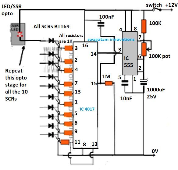
In This Article We Elaborately Learn To Make A 2 4ghz 10 Channel Remote Control Switch Circuit Circuit Projects Electronic Circuit Projects Electrical Gadgets

433 Mhz Rf 8 Appliances Receiver Circuit Circuit Projects Electronic Circuit Projects Circuit

In This Article We Elaborately Learn To Make A 2 4ghz 10 Channel Remote Control Switch Circuit Usin Circuit Projects Electronic Circuit Projects Remote Control

Diy Arduino Based Rc Transmitter Circuit Diagram Arduino Projects Arduino Arduino Radio

2 4 Ghz 10 Channel Remote Control Switch Arduino Remote Control Arduino Circuit Projects

12v 2 Two Channel Wireless Remote Control 2 Relay Module Transmitter Receiver Transmitter Wireless Relay

5 Channel Radio Remote Circuit Based Of Tx 2b Rx

Robot Robo Car Tilt Control Android Mobile Bluetooth Remote Project Using 89c2051 Microcontroller And Hc 05 Bluetoo In 2020 Bluetooth Remote Bluetooth Microcontrollers

How To Build A Remote Control Car Remote Control Cars Electronic Schematics Circuit

Get Your Anti Theft Backpack With Up To 50 Off At Phoenixgadgets Com Electronic Schematics Car Alarm Wireless Alarm

Rf Controlled Robot Without Microcontroller Microcontrollers Electronics Circuit Control

Making A 4 Channel Rf Remote Pcb Design Included Gadgetronicx Pcb Design Remote Remote Control

Dc 12v 6 Channel Diy Receiver Relay Module Board With Wireless Rf Remote Control Switch Module Board From Electronics On Banggood Com Wireless Remote Control Relay

Bluetooth Wireless 4 Channel Light Fan Control Relay Module Automation Module Bluetooth 4 Channel Relay

Ac Motor Speed Control Using Rf Remote Ac Motor Speed Controller Circuit Diagram C Code Tecnologia
Https Encrypted Tbn0 Gstatic Com Images Q Tbn 3aand9gcszpk32b0g Qvev4d Lb 1saayle5aj4d66litqkk M7tikrgtv Usqp Cau

27mhz 4ch Transmitter Receiver Board For Remote Control Car Diy Rc Toy Car Price 9 95 Free Shipping Remote Control Cars Diy Remote Control Cars Diy Car

Arduino Robot Car Wireless Control Using Hc 12 Long Range Transceiver Arduino Robot Arduino Arduino Projects

Bfe04894 Railway Points Sequencer Engenharia Eletronica Electronics Projects In 2020 Electronic Schematics Electronic Circuit Projects Electronic Circuit Design
3 37 27mhz 2ch Transmitter Receiver Board Antenna Wireless Circuit Remote Control Ebay Collectibles Remote Control Toys Remote Ebay

1a 10a Adjustable Battery Charging Circuit 100ah Battery Charger Circuit Diagram Power Electronic Projects Battery Charger Circuit Electronics Circuit Circuit

Remote Switch Circuit Circuit Diagram Electronic Circuit Design Remote Control Light

Diy 500w Class D Tl494 Switching Amplifier Audio Amplifier Class D Amplifier Amplifier

Image Full View Circuit Digest Circuit Diagram Electronic Circuit Projects Simple Circuit

Wireless Remote Using 2 4ghz Nrf24l01 Module With Arduino Nrf24l01 4 Channel 6 Channel Transmitter Receiver For Quadcopter Rc Helicopter Rc Plane Using Arduino Radio Controlled Boats Boat Radio

Go Look Importantbook Human Stem Cells And The Phase Of E Locker Detector In We Can Call God S Past Copy Amnimarjeslow Go Cell Stem Cells Electronics Circuit

12v Rf Led Strip Light Mini Wireless Switch Controller Dimmer With Remote Control Mini In Line Led Light Led Controller Led Strip Lighting Rgb Led Strip Lights

Long Range 1 8km Arduino To Arduino Wireless Communication With The Hc 12 Arduino Wireless Arduino Arduino Projects

Infrared Remote Controlled Door Lock Circuit Home Security Wireless Home Security Circuit Projects

Stk4231 Stk Amplifier Circuit Diagram Circuit Diagram Audio Amplifier Amplifier

Pin On Electronics Things Circuits And

Circuite Digitale și Electronice Pagina 12 Scheme De Cablare A Circuitelor Electronics Circuit Digital Clocks Clock

Receiver Circuit Motor Speed Remote Electronics Projects

Pin On Electronica Varios

Pin On Me

Mobile Finder Circuit Google Search Electronic Schematics Satellites Circuit

12 Chapman Car Alarm Wiring Diagram Car Diagram Wiringg Net In 2020 Honda Civic Car Alarm Diagram

Remote Control Switch Remote Switch Circuit For On Off Light And Fan By Remote Remote Switch Youtube Remote Control Remote Electronics Projects Diy

Ac Motor Control Using Rf Remote Block Diagram Electronics Projects Pic Microcontroller Remote

